
Standards led, practical steps for engineers to deploy redundant camera networks: MRP, dual homing, and aggregation patterns, commissioning checks, and...
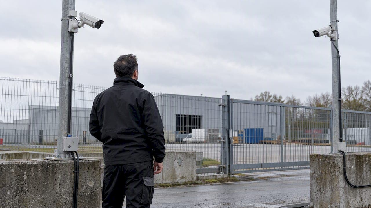
30–90 Day Pilot Validates Redundant Camera Networks for Engineers

For fault-tolerant camera networks, three architecture families cover most deployments: MRP rings for industrial and linear topologies, dual-homing for predictable access-to-core resilience, and active-active aggregation for high-throughput, multi-path environments. Each trades differently on convergence time, bandwidth overhead, and cost, so the right choice depends on how much downtime your operation can tolerate before it becomes a liability.
TL;DR:
- MRP rings suit linear or dispersed camera layouts, with recovery times of 30, 200, or 500 milliseconds depending on the profile and vendor compatibility.
- Dual-homing improves resilience by connecting cameras or switches to two upstream devices, with variations including separate uplinks or dual power sources.
- Active-active aggregation provides near-instant failover by treating multiple links as one, but requires IGMP snooping to prevent stream duplication during outages.
- Stacking redundancies across power, network, storage, and software layers prevents a single failure from causing a total loss of surveillance coverage.
- Testing redundancy through failure simulations, such as pulling links or disconnecting power, is critical to validate recovery times align with operational SLAs.
Table of Contents
- Architecture Patterns for Redundant Camera Networks
- Layering Redundancy Across Power, Network, Recording, and Software
- Design Rules for Bandwidth, Coverage, and Recovery Targets
- A Commissioning Checklist That Catches Failures Before They Happen
- What an Integrator Pilot Revealed About Dual-Path Resilience
- Network Redundancy Versus Sensor Redundancy: Where to Spend First
- How We Help You Design and Pilot Redundant Camera Networks
- FAQ
- Sources
Architecture Patterns for Redundant Camera Networks
MRP rings (per IEC 62439-2) fit linear or geographically distributed camera runs, like perimeter fencing or long corridors, where a tree topology would create a single point of failure at every switch. One switch is configured as the Media Redundancy Manager (MRM), coordinating the ring, while the rest act as Media Redundancy Clients (MRCs). Recovery profiles come in 30 ms, 200 ms, and 500 ms variants, and faster profiles demand tighter vendor compatibility checks before commissioning.
Dual-homing connects each camera, or each access switch, to two independent upstream devices. This pattern shows up in three common forms:
- Camera-to-two-access-switches, used when individual camera uptime matters more than network-wide resilience.
- Access-switch-to-two-cores, the more typical enterprise pattern, which isolates a single switch failure from taking down an entire segment.
- Dual PoE sourcing paired with dual uplinks, which protects against both link failure and local power loss at the switch.
Active-active aggregation using MLAG or LACP spreads camera traffic across two or more physical links treated as one logical path. Unlike MRP's ring convergence, failover here is close to instantaneous because both paths carry traffic simultaneously rather than one standing by. The catch is multicast handling: camera streams using multicast for multi-viewer access need careful IGMP snooping configuration across both aggregation members, or you get duplicate or dropped frames during a link event. A mid-size campus with 200 to 400 cameras across multiple buildings often combines all three: MRP rings within buildings, dual-homed uplinks between buildings, and active-active aggregation at the core.
Layering Redundancy Across Power, Network, Recording, and Software
A ring or dual-homed link protects against one kind of failure. Real resilience comes from stacking independent redundancy at every layer, so a single bad day, a blown PSU, a severed conduit, or a corrupted recording share doesn't cascade into a total outage.
- Power. Dual PSU switches, DC feed options for industrial cabinets, and local battery backup at camera-adjacent PoE injectors keep cameras recording through utility interruptions that outlast your UPS runtime.
- Network. Segment camera traffic onto its own VLAN or physical domain, separate from general office data, so a broadcast storm or misconfiguration elsewhere doesn't touch surveillance uptime.
- Recording. Edge storage on the camera itself keeps recording locally during a network outage, and central recorders should automatically retrieve the missing footage once connectivity returns, a pattern recommended in Singapore's VSS standard for buildings. The edge storage feature brief notes that automatic retrieval suits short outages, while scheduled or manual retrieval fits bandwidth-constrained sites better.
- Application. VMS clustering with replicated configuration databases prevents a single server crash from blinding operators, but it introduces split-brain risk if two nodes both believe they're primary. Quorum-based arbitration, rather than a simple heartbeat, avoids that failure mode.
Design Rules for Bandwidth, Coverage, and Recovery Targets
Three numbers should anchor every redundant camera design: coverage depth, bandwidth headroom, and your actual recovery time requirement.

K-coverage measures how many cameras observe a given point; raising K from 1 to 2 improves fault tolerance against a single camera or sensor failure, but it also multiplies bandwidth and processing load, a trade-off the academic literature on K-coverage treats as a balancing act rather than a simple "more is better" rule.
Bandwidth budgeting should assume bursts, not averages. Alarm-triggered recording, simultaneous motion events, and operator-initiated playback can spike traffic well above steady-state levels, which is why planning for 2 to 3 times peak load is standard practice rather than a conservative outlier.
- Consolidate overlapping fields of view where possible: coordinated transport of correlated streams can recover meaningful quality gains under the same bandwidth cap, according to research on in-network video consolidation.
- Enforce ONVIF compliance so failover doesn't silently break stream negotiation between mixed-vendor cameras and recorders.
- Match recovery profile to business impact rather than defaulting to the fastest option available.
Media Redundancy Protocol recovery profiles of 30 ms, 200 ms, and 500 ms, as implemented on industrial switch platforms, give engineers a direct way to map tolerance to configuration: a trading floor or secure perimeter justifies 30 ms, while a warehouse loading dock rarely needs anything faster than 500 ms.
A Commissioning Checklist That Catches Failures Before They Happen
Redundancy that hasn't been tested under failure conditions is a design assumption, not a working system. Run through this sequence before handing a network to operations:
- MRP verification. Confirm MRM and MRC roles are assigned correctly, verify the ring reports a closed state, then pull a link and measure actual convergence against the configured profile.
- Loop-avoidance interaction. Check how MRP and spanning tree interact at ring boundary ports; mixing the two without explicit port role configuration is a common source of unexpected blocking.
- Power failure simulation. Disconnect one PSU per switch and confirm PoE continuity, then isolate network connectivity entirely and verify cameras continue local edge recording.
- Edge-storage reconciliation. Restore connectivity after a simulated outage and confirm the NVR automatically retrieves the missing segment with continuous timestamps, no gaps, no duplicate frames.
- Operational load tests. Saturate bandwidth intentionally, measure actual failover recovery time against your target, and confirm health telemetry and alerting fire correctly during the event.
Document every result against a target SLA. A ring that converges at 180 ms when the spec called for 30 ms isn't a minor variance, it's a design defect that needs root-causing before go-live.
Pro Tip: Run your power-loss and network-loss tests separately before combining them. A simultaneous dual failure masks which redundancy layer actually caught the first fault.

What an Integrator Pilot Revealed About Dual-Path Resilience
A dual-path and warm-standby pattern, documented in our field notes on redundant CCTV communications, paired a primary fiber path with a cellular or secondary wired backup, keeping recording gaps during a primary outage short enough that automated retrieval closed them without operator intervention.
- Bandwidth planning during the pilot accounted for burst load from simultaneous alarm triggers, not just steady-state streaming.
- Camera health was tracked continuously using RTSP stream checks rather than relying on ping reachability alone.
- Firmware discipline, patched on a fixed schedule, prevented the version drift that otherwise breaks failover behavior between cameras and recorders over time.
A 30 to 90 day pilot window is enough to validate uptime targets, confirm retrieval automation works under real network conditions, and catch AI health-check false positives before a full rollout commitment.
Network Redundancy Versus Sensor Redundancy: Where to Spend First
Engineers often default to hardening the network fabric first, but for many sites, adding a second camera at a critical point or pushing more intelligence to the edge closes a bigger resilience gap per dollar than a third redundant switch. Network investment pays off once scale or geographic spread makes single points of failure unavoidable. Below that threshold, operational simplicity usually beats theoretical resilience, so a 30 to 90 day pilot scoped around your actual risk points, not every possible failure mode, tends to answer the "where to spend first" question better than a spec sheet ever will.
— Eumir
How We Help You Design and Pilot Redundant Camera Networks
We design and validate camera network redundancy through our Solution Integration service, combining MRP, dual-homing, and active-active patterns with the monitoring capabilities in BeyondWatch and the automated oversight built into BeyondPatrol. Pilot engagements often include a 30 to 90 day timeframe with defined uptime targets, retrieval automation testing, and camera health checks to provide evidence before a full rollout commitment.
If your network needs a redundancy architecture that holds up under an actual link or power failure, not just on paper, request a pilot scope with our integration team.
FAQ
What does a redundant network mean in camera system design?
A redundant network means that if one path, device, or power source fails, traffic and recording continue through an alternate route without a complete loss of coverage. In camera systems this typically combines network-layer failover (MRP, dual-homing) with recording-layer backup like edge storage.
Is redundancy worth the added cost in a camera network?
Redundancy is worth the investment where downtime carries real operational or safety risk, such as regulated facilities or high-traffic sites, but it adds real cost in switches, links, and bandwidth. IMDA's resilience guidance recommends a business impact analysis to decide how much redundancy a given site actually needs rather than applying a blanket standard.
Which network topology gives the most redundancy for cameras?
MRP rings and active-active aggregation generally offer the strongest resilience, since both maintain connectivity through a single link or node failure without manual intervention. The right choice depends on your topology: rings suit linear or distributed camera runs, while aggregation suits high-throughput core connections.
What does redundancy mean in the context of camera network cybersecurity?
Redundancy in a security context means that a compromised or failed network path doesn't also take down your evidence trail or monitoring capability. Segmenting camera traffic, enforcing ONVIF compliance, and keeping firmware current all reduce the chance that a single exploited device cascades into a full outage.
How do I test whether my redundant camera network actually works?
Simulate real failures: pull a link to measure MRP convergence time, disconnect a PSU to confirm PoE continuity, and cut network access to verify edge recording and automatic retrieval behave as designed. Document actual recovery times against your target SLA rather than assuming the configuration will perform as specified.
Sources
- Redundancy Protocol Configuration Guide, Cisco Catalyst IE31xx Series Switches - Media Redundancy Protocol Cisco Catalyst IE3100 Rugged Series
- VSS Standard for Buildings (Singapore Police Force)
- Edge storage feature brief (Milestone)
- K-coverage design metric (academic paper)
- Guidance for resilience and security of data centres (IMDA)
Recommended
Read More Articles
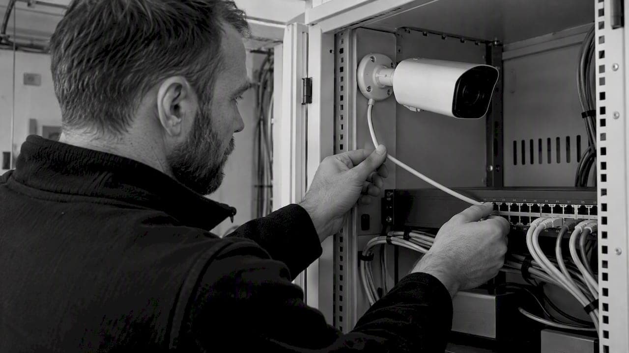
RTSP Security Risks: Integrators Must Block Exposed Ports 554 and 8554
See how integrators can reduce RTSP security risks: close exposed ports 554 and 8554, secure camera access, and verify each deployment with practical checks.
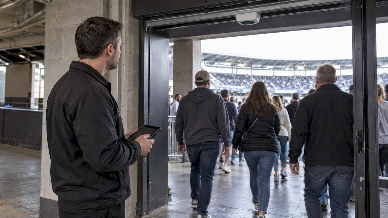
Require MAEpp and X Accuracy Before You Buy People Counting Systems
Verify people counting accuracy by demanding MAEpp, X Accuracy, and directional-bias reports. Validate on-site with at least 100 events per direction...
30 Day Pilot Proves Video Analytics Accuracy for Security Teams
Validate video analytics accuracy with scenario tests, camera tuning, transfer learning and a 30 day edge first pilot for security teams.
Installers: Get sub millisecond CCTV time with an on site NTP server
Installer checklist for secure on site NTP for CCTV. Includes chrony setup, device config, troubleshooting, and forensic timestamp protection.
Let's Build YourSecurity Ecosystem.
Whether you're a System Integrator, Solution Provider, or an End-User looking for trusted advisory, our team is ready to help you navigate the BeyondSensor landscape.
Direct Advisory
Connect with our regional experts for tailored solutioning.