
Discover how to design secure video walls for 24/7 control rooms, ensuring robust systems, ergonomic layouts, and optimal operational workflows.
Secure Video Wall Design for Security Control Rooms
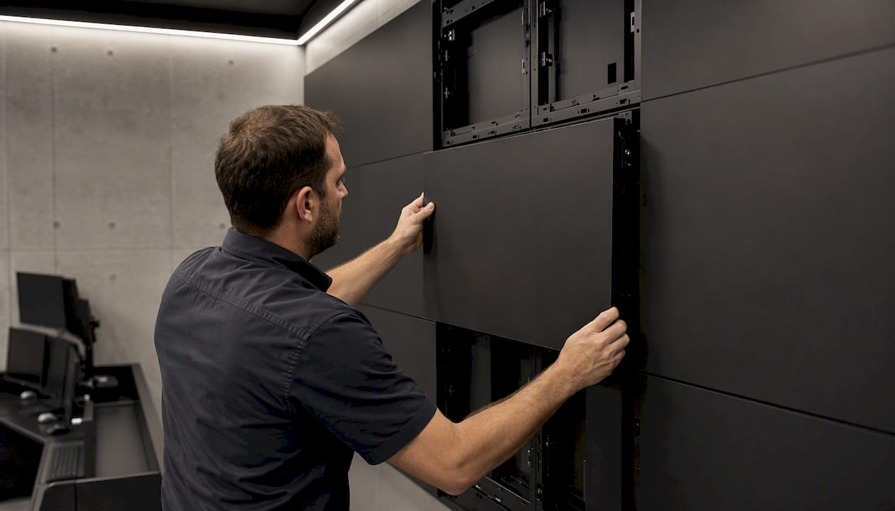
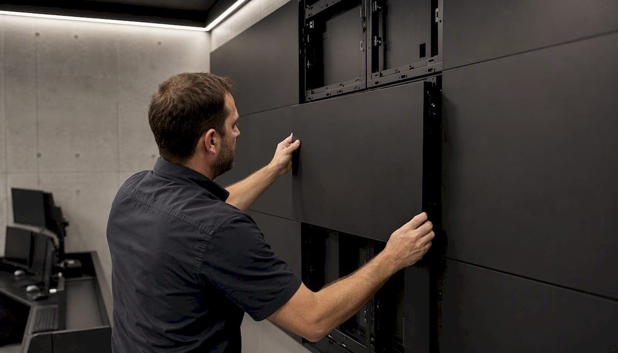
A secure, operationally driven AV-over-IP video wall architecture with explicit redundancy, role-based operator controls, and documented commissioning tests is the right baseline for any 24/7 security control room. Video wall design security is not a hardware decision alone. It is a systems discipline that starts with your operational use cases and ends with signed acceptance tests. Before you specify a single display panel, design the wall around operational workflows and content ownership, because those decisions determine every downstream hardware and software choice.
Non-negotiable design elements:
- Defined use cases and stakeholder control privileges before any hardware selection
- AV-over-IP or dedicated processor distribution with documented failover behavior
- N+1 power, hot-standby controllers, and redundant network paths
- Ergonomic sightline analysis and seated eye-height baseline for operator positions
- Cybersecurity controls: RBAC, SSO, audit logs, network segmentation, and firmware policy
- Factory Acceptance Testing (FAT) and Site Acceptance Testing (SAT) with traceable test logs
- Physical tamper protection and secure mounting for all display and processing hardware
Next step: Authorize a site survey and include commissioning test requirements in your RFP before vendor conversations begin.
Pro Tip: Write your use-case list before you write a single line of your RFP. Vendors who cannot map their architecture to your specific incident-load scenarios are not the right fit, regardless of panel specifications.
Key Takeaways
A secure control room video wall requires operational use-case mapping, AV-over-IP architecture with explicit failover, ergonomic sightline analysis, and signed FAT/SAT acceptance tests before handover.
| Point | Details |
|---|---|
| Use-case driven layout | Map stakeholder control privileges and incident-load scenarios before specifying any hardware. |
| Distribution architecture | AV-over-IP with VLAN segmentation and QoS is the scalable baseline; document failover time and test it. |
| Redundancy at every layer | N+1 power, hot-standby controllers, mirrored content servers, and dual network paths are non-negotiable for 24/7 SLAs. |
| Ergonomics and sightlines | Bottom wall edge at approximately 4 feet for seated operators; limit primary-zone eye rotation to 15 degrees |
| Beyondsensor integration | Beyondsensor's sensor-to-dashboard integration and deployment planning tools support the full source-routing and analytics layer for security video wall deployments. |
Table of Contents
- What control-room stakeholders actually need from a video wall
- What architecture should power your security video wall?
- How do display type and sizing affect operator performance?
- How should operators be positioned for sustained situational awareness?
- What does 24/7 uptime actually require from your video wall?
- How do you integrate VMS, SIEM, and analytics without creating security gaps?
- What does a solid installation and commissioning process look like?
- How do you evaluate vendors and build a procurement-ready RFP?
- A reusable sample WBS, milestones, and acceptance test snippets
- What most video wall projects get wrong
- How Beyondsensor supports your video wall deployment
- Sources
What control-room stakeholders actually need from a video wall
Every security operations center (SOC), network operations center (NOC), or global security operations center (GSOC) has a different mix of stakeholders, and each one needs a different relationship with the wall. Mapping those needs early prevents the most common design failure: a wall that looks impressive in a demo but cannot support the actual shift workflow.
Stakeholder view and control requirements
| Stakeholder | Primary view need | Control privilege |
|---|---|---|
| Operator (tier 1) | Camera grids, alert queue, incident tickets | Promote sources to personal zone; acknowledge alerts |
| Shift lead | Incident overview, escalation queue, operator status | Promote to shared wall zones; override operator layouts |
| Incident manager | Full incident timeline, promoted camera, SIEM drill-down | Full wall control; lock shared zones during active incident |
| Facilities / IT | System health, network telemetry, hardware status | Read-only on operational zones; write on infrastructure zone |
| Executive / visitor | Summary dashboard, KPI tiles, incident status | Read-only; no promotion rights |
Use cases that drive layout and control design
Four use cases shape the physical layout and software configuration of any control room video wall:
- Routine watch: Operators monitor a steady-state camera grid and alert queue. The wall needs clear zoning, consistent source labeling, and stale-data indicators so nothing goes unnoticed during low-activity periods.
- Incident response: An active event triggers promoted views, cross-source correlation, and real-time SIEM overlays. The wall must support rapid source promotion without disrupting other operators' zones.
- Post-event review: Supervisors replay recorded footage alongside timeline data. This requires VMS integration with frame-accurate playback and the ability to pull archived sources onto the wall without affecting live feeds.
- Executive briefing: Leadership needs a clean, summarized view. A dedicated layout preset that hides raw alert queues and shows KPI tiles is the right answer here.
Mandatory requirements for 24/7 operations:
- Uptime target of 99.9% or better, with SLA language specifying mean time to repair (MTTR) and escalation paths
- Data-handling constraints documented per source: which feeds are classified, which are PII-bearing, and which can be displayed in shared zones
- Air-gap options for classified networks, with physical separation of display signal paths where required
- Video retention and privacy rules aligned to applicable state and federal regulations (e.g., CCTV retention policies, HIPAA where health-facility cameras are involved)
- Physical tamper protection: locked enclosures for processing hardware, cable management that prevents accidental disconnection, and access logging for the server room
Security monitoring workflows for facility teams should be documented before the wall design is finalized, because the workflow determines zone count, layout presets, and operator control granularity.
What architecture should power your security video wall?
The distribution method you choose determines scalability, latency, security posture, and long-term maintenance cost. Three architectures dominate control-room deployments today.
Source classes and routing
Typical sources in a security control room include: IP camera streams from a VMS, SIEM and EDR dashboards, SCADA or building management system (BMS) telemetry, NVR outputs, operator workstations, and external data feeds (weather, traffic, public safety CAD). Each source class has different latency tolerance, resolution, and authentication requirements. Routing all of them through a single unmanaged switch is a reliability and security failure waiting to happen.
Distribution method comparison
AV-over-IP encodes sources at the edge using hardware or software encoders and routes compressed video over a standard IP network to decoder nodes at each display. AV-over-IP architectures simplify scaling and source routing and offer hardware-agnostic expansion, but they require explicit network QoS policies, VLAN segmentation, and active monitoring. Latency typically runs 50–200ms depending on codec and network load, which is acceptable for surveillance but requires verification for real-time telemetry.
Dedicated video wall processors use proprietary hardware matrices to route sources directly to display tiles. Latency is lower (often under 50ms), and the architecture is simpler to troubleshoot, but scaling beyond the processor's fixed input count requires additional hardware and can create proprietary lock-in.
Encoder/decoder appliances sit between these two approaches: purpose-built hardware with deterministic latency and better support for lossless or near-lossless codecs (NDI, JPEG2000), at a higher per-port cost than software AV-over-IP.
Bandwidth planning guidance:
- A 1080p RTSP stream at H.264 typically consumes 4–8 Mbps per source
- A 4K NDI stream requires approximately 125–250 Mbps per source
- Browser-based dashboards (SIEM, telemetry) vary widely; budget 5–20 Mbps per rendered instance
- For a 32-source wall with mixed 1080p camera feeds and dashboards, plan for at least a 10 Gbps core switch with redundant uplinks
Redundancy and segmentation architecture: Place video wall traffic on a dedicated VLAN, separate from corporate IT and from the camera/sensor network. Use dual network paths (active/standby or LACP bonding) between the encoder layer and the display controller. Mirror the content server to a hot-standby instance on a separate physical host. Design for source isolation so a failed camera, dashboard token expiry, or single-source authentication failure does not blank the entire canvas.
Intelligent sensing technologies feeding operational dashboards should be routed through the VMS or a dedicated encoder, not directly to the wall controller, to maintain source isolation and authentication boundaries.
How do display type and sizing affect operator performance?
Display selection is where many projects go wrong. Planners over-specify resolution on large walls where pixel pitch already limits visible detail, or under-specify brightness for rooms with ambient light from windows or status boards.
Pixel pitch, viewing distance, and content type
The minimum comfortable viewing distance for a given pixel pitch follows a straightforward rule: multiply the pixel pitch in millimeters by roughly 1,000 to get the minimum viewing distance in millimeters. A 1.9mm pitch panel is readable at approximately 1.9 meters. For a control room where operators sit 2.5–4 meters from the wall, a pixel pitch of 2.5–4mm is the practical range for direct-view LED. LCD panels with near-zero bezels work well at 3–6 meters for mixed camera and dashboard content.
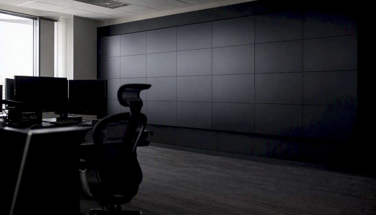
Ergonomic sightline analysis places the bottom edge of the wall at approximately 4 feet above the finished floor for seated operators, and limits maximum eye rotation to a moderate ergonomic threshold commonly accepted for operator comfort from the operator's neutral sightline. Ceiling height, console depth, and the number of operator rows all change these numbers in practice, which is why a site-specific sightline study is worth doing before finalizing wall dimensions.
LCD vs. direct-view LED: key tradeoffs
| Criteria | LCD (narrow-bezel) | Direct-view LED |
|---|---|---|
| Best for | Moderate viewing distances (3–6m), mixed content, budget-sensitive deployments | Close viewing, large-format walls, high-ambient-light rooms |
| Pixel density | High native resolution per panel; 4K panels common | Pixel pitch dependent; fine pitch (1.2–2.5mm) needed for close viewing |
| Bezel impact | Thin bezels acceptable for most content; visible on maps | Zero bezel; seamless image across full canvas |
| Lifetime maintenance | Backlight replacement at high hours; individual panel swap | LED module replacement; longer rated life but higher per-module repair cost |
| Installation complexity | Modular, lighter panels; standard mounting hardware | Heavier cabinets; requires precision alignment and calibration |
For LED panel installation and physical mounting considerations, the Absen LED M2.9 Pro panel is one example of a fine-pitch direct-view LED module used in professional deployments, with the rigging and calibration requirements that come with that format.
Pro Tip: For multi-row walls, tilt the upper row 5–10 degrees toward the operator to maintain consistent brightness and color uniformity across the full viewing angle. Most LCD panels lose significant brightness beyond 20 degrees off-axis.
How should operators be positioned for sustained situational awareness?
Operator fatigue is a real operational risk. A wall that forces operators to crane their necks or swivel repeatedly between zones degrades alertness over a 12-hour shift. The physical layout of consoles and the software zoning of the wall need to be designed together.
Operator positioning guidelines:
- Seated eye height baseline: 44–48 inches from finished floor for a standard ergonomic chair at full height
- Primary content zone: within 15 degrees of the operator's neutral horizontal sightline
- Maximum head rotation for frequently accessed zones: 30 degrees left or right
- Secondary zones (incident escalation, system health): up to 45 degrees, accessed intentionally rather than monitored continuously
Zoning the wall for watch vs. incident workflows
A well-zoned wall separates standing-watch content (camera grids, alert queues) from incident-lane content (promoted sources, SIEM drill-down, incident tickets). During routine watch, the incident lane sits in a ready state with a named layout preset. When an incident is declared, the shift lead promotes the relevant sources into the incident lane without disturbing the watch zone. This separation keeps the wall readable under pressure. It is the core design principle behind SOC wall zoning for incident load.
Alert handling rules for operators:
- Promoted views must carry a visible source label, timestamp, and data-freshness indicator
- Stale data (feed older than a configurable threshold) triggers a visual warning tile, not a blank tile
- Source promotion requires authentication at the operator's privilege level; anonymous promotion is disabled
- Quick drill-down paths (one click from alert tile to full-screen camera or SIEM event) reduce response latency
- Layout presets for common incident types (perimeter breach, access control event, fire alarm) are pre-configured and tested before go-live
Optimizing physical security workflows with advanced sensors informs how sensor-triggered alerts should be routed to the wall's alert queue, so operators receive actionable context rather than raw sensor data.
Pro Tip: Pre-build at least five named layout presets for your most common incident types and test them in a tabletop exercise before commissioning. Operators who have rehearsed a layout change under simulated pressure execute it in seconds; operators discovering it for the first time during a real incident take minutes.
What does 24/7 uptime actually require from your video wall?
Mission-critical SLAs are not achieved by buying premium hardware. They are achieved by designing redundancy into every layer and then testing it before the system goes live.
Redundancy checklist:
- Power: N+1 UPS on all processing hardware; dual PSUs in video wall controllers and servers; generator backup for the control room circuit
- Controllers: hot-standby controller with automatic failover; failover time documented and tested during commissioning
- Network: dual physical paths between encoder layer and display controller; spanning tree or LACP configured and verified
- Content servers: mirrored active/standby pair on separate physical hosts; replication lag monitored
- Display hardware: at least one spare panel of each type on-site; spare LED modules for direct-view installations
Uptime SLA language to include in contracts
| SLA element | Minimum acceptable language |
|---|---|
| Availability target | 99.9% measured monthly, excluding scheduled maintenance windows |
| MTTR for critical failures | 4 hours on-site response; 8 hours to restore full wall function |
| Scheduled maintenance | Advance notice recommended; maintenance windows outside peak operational hours |
| Spare parts availability | Critical spares held on-site or within 2-hour delivery radius |
| Remote monitoring | Vendor-provided health telemetry with alerting to operations team |
Maintenance schedule and monitoring telemetry:
- Monthly: review hardware health logs (fan speeds, temperatures, power supply voltages), check network latency between encoder and decoder nodes, verify failover behavior with a controlled test
- Quarterly: clean display panels and ventilation paths, update firmware on controllers and encoders per the approved change-management process, review audit logs for anomalous access patterns
- Annually: full sightline and brightness uniformity check, review SLA performance against contract, update spare parts inventory
Use Beyondsensor's server rack space planner to size your hardware enclosures and plan spare capacity before procurement, so redundant components fit within the physical infrastructure from day one.
How do you integrate VMS, SIEM, and analytics without creating security gaps?
Integration is where video wall design security becomes a cybersecurity problem. Every source you add to the wall is a potential attack surface if it is not properly authenticated, segmented, and monitored.
Integration flow
A typical SOC wall integration path runs: IP cameras and access control systems feed a VMS; the VMS outputs streams via RTSP or an SDK to the video wall encoder layer. SIEM platforms (Splunk, IBM QRadar, Microsoft Sentinel) render dashboards in a browser or dedicated client that is captured by a software encoder or a dedicated workstation connected to the wall controller. Telemetry and EDR feeds follow the same browser-capture or API-render path. Operator workstations connect via KVM-over-IP or direct encoder to allow personal zone control.
A SOC video wall should expose multiple operational layers simultaneously: SIEM alerts, telemetry, camera grids, and incident tracking. Size and zone the wall around incident load, not the nominal dashboard count during quiet periods. A wall designed for quiet-state monitoring will fail operationally the moment a real incident demands simultaneous source promotion across all zones.
Overlay and metadata guidelines:
- Every source tile displays: source name, feed timestamp, data-sensitivity classification, and last-refresh indicator
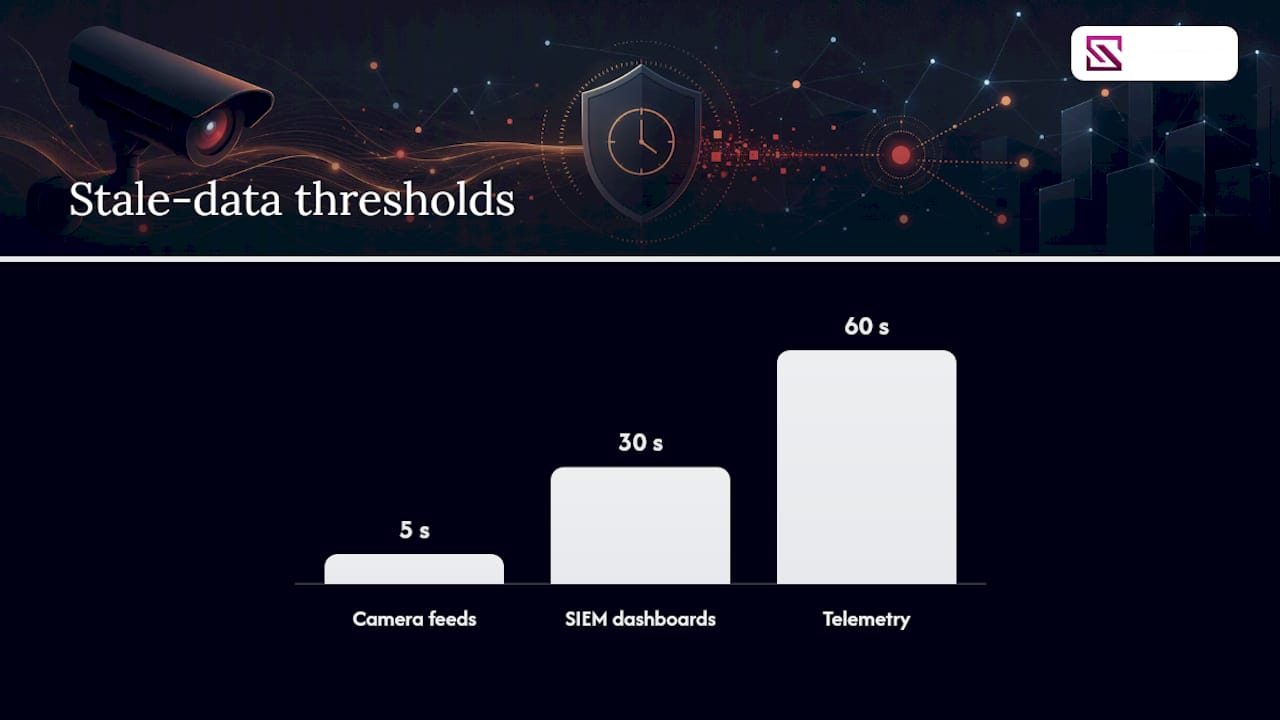
- Stale-data thresholds are set per source class (camera feeds: 5 seconds; SIEM dashboards: 30 seconds; telemetry: 60 seconds)
- Incident overlays (bounding boxes, alert annotations from video analytics) are rendered by the VMS or analytics platform, not by the wall controller, to keep the controller's processing load predictable
Security and privacy controls:
- On-premises control plane for classified or air-gapped environments; cloud-managed control plane only for unclassified networks with explicit approval
- RBAC, SSO integration, audit logs, and hot-standby servers are baseline requirements for any mission-critical control platform
- Firmware update policy: all wall controllers, encoders, and decoders on a documented patch cycle; no internet-facing management interfaces
- Network segmentation: video wall management traffic on a dedicated VLAN, isolated from both the corporate network and the sensor/camera network
- Physical access to processing hardware restricted to authorized personnel; access logged
Physical security integration best practices cover the system-of-record decisions that determine which platform owns source authentication and how changes propagate to the wall.
What does a solid installation and commissioning process look like?
A well-run installation follows a structured work breakdown and ends with signed acceptance tests. Projects that skip FAT and SAT steps routinely discover integration failures after the client has taken occupancy, which is the most expensive time to fix them.
Project phases
- Site survey: Measure room dimensions, ceiling height, ambient light levels, console positions, and existing infrastructure (power, network, conduit). Document sightline constraints and operator count.
- Design and engineering: Produce rack diagrams, cable schedules, network topology, and sightline drawings. Submit for client review and approval before procurement.
- Procurement: Issue purchase orders with lead times documented; flag long-lead items (custom LED cabinets, specialized encoders) for early ordering.
- Installation: Mount displays, install processing hardware in racks, run and label all cabling, configure network switches and VLANs.
- Commissioning (FAT): Factory Acceptance Testing at the integrator's facility or staging area; verify all sources, failover behavior, and software configuration before shipping to site.
- Site commissioning (SAT): Site Acceptance Testing after installation; repeat all FAT tests in the live environment, add site-specific tests (ambient light, sightline verification, operator workflow walk-through).
- Handover and training: Deliver all documentation, conduct operator and administrator training, transfer credentials.
Commissioning test checklist
- Display uniformity: brightness and color temperature consistent across all tiles within ±5% (or per manufacturer spec)
- Input failover: simulate primary source failure; verify hot-standby source activates within the documented failover time
- Latency test: measure end-to-end latency from camera capture to display output; document against the specified maximum
- Authentication and role testing: verify each operator role can access only its permitted zones and controls; test SSO integration and session timeout behavior
- Stale-data handling: disconnect a source feed; verify the stale-data indicator appears within the configured threshold
- Physical security: verify all rack enclosures lock, cable management is secure, and access logging is active
Required handover deliverables
| Deliverable | Description |
|---|---|
| As-built diagrams | Final rack, cable, and network topology drawings reflecting actual installation |
| Credentials handover | All system passwords, certificates, and API keys transferred to client in a secure credential store |
| Test logs | Signed FAT and SAT test records with pass/fail results and any deviations noted |
| Spares list | Itemized list of on-site spares with part numbers and reorder sources |
| Maintenance plan | Scheduled maintenance tasks, intervals, and responsible parties |
LED screen installation and calibration guidance covers rigging, power distribution, and calibration steps that apply directly to direct-view LED wall installations in control rooms.
How do you evaluate vendors and build a procurement-ready RFP?
Vendor selection for a mission-critical video wall is a risk management decision as much as a technology one. The questions below separate vendors with genuine 24/7 operational experience from those selling conference-room AV at a control-room price.
RFP questions to ask every vendor:
- What is your documented failover time from primary to hot-standby controller, and how is it tested?
- How does your platform handle source authentication expiry without blanking the display canvas?
- What network segmentation architecture do you recommend, and what QoS policies are required?
- Describe your RBAC model: how are roles defined, how are changes audited, and how is SSO configured?
- What is your firmware update process, and how are updates tested before deployment to production?
- Provide three references for 24/7 security control room deployments of comparable scale.
- What is your on-site response time SLA, and where are your nearest field engineers?
Vendor evaluation rubric
| Criterion | Weight | What to look for |
|---|---|---|
| Use-case fit | High | Can the vendor map their architecture to your specific incident-load scenarios? |
| Resolution and pixel density | Medium | Does the proposed pixel pitch match your viewing distance and content type? |
| Redundancy features | High | Hot-standby controller, N+1 power, dual network paths, documented failover time |
| Scalability | Medium | Can the system add sources and display tiles without a full redesign? |
| Control and software features | High | RBAC, SSO, audit logs, named layout presets, multi-operator control |
| Total cost of ownership | High | Include hardware, software licensing, maintenance contracts, and spares over 5 years |
| Installation complexity | Medium | Lead time for custom hardware, integrator experience with similar deployments |
TCO input table for vendor comparison
Request these figures from each vendor in writing during the RFP process:
A reusable sample WBS, milestones, and acceptance test snippets
The work breakdown structure below is designed to be copied into an RFP or project plan. Adjust task durations to your site complexity and procurement lead times.
Sample project milestones
| Milestone | Acceptance criteria | Owner sign-off |
|---|---|---|
| M1: Site survey complete | Survey report delivered; sightline drawing approved by operations manager | Integrator + Facility Planner |
| M2: Design approved | Rack diagrams, cable schedules, and network topology signed off | Integrator + IT + Security Ops |
| M3: FAT complete | All FAT test cases passed; deviations documented and resolved | Integrator + Client PM |
| M4: SAT complete | All SAT test cases passed in live environment; operator walk-through signed off | Integrator + Security Ops Manager |
| M5: Training complete | Operator and admin training delivered; attendance records signed | Integrator + HR/Training |
| M6: Handover complete | All deliverables received; credentials transferred; maintenance plan accepted | Client PM + IT |
Numbered WBS tasks
- Conduct site survey: measure room, document power and network infrastructure, photograph existing console layout
- Produce sightline drawing and ergonomic analysis for operator positions
- Draft rack diagrams and cable schedules; submit for client review
- Produce network topology diagram showing VLAN segmentation and QoS policy
- Issue RFP or purchase orders; confirm lead times for long-lead items
- Receive and inspect hardware; verify against bill of materials
- Install display mounting structure and verify alignment
- Mount and cable display panels; verify power and signal continuity
- Install processing hardware in racks; configure network switches and VLANs
- Execute FAT test plan: source routing, failover, authentication, latency, uniformity
- Ship and install on-site; repeat SAT test plan in live environment
- Conduct operator training session; deliver administrator guide
- Transfer credentials and documentation; obtain client sign-off on all deliverables
Acceptance test snippets for RFP inclusion:
- Source failover test: Disconnect the primary encoder for Source X. The system shall activate the designated hot-standby source within [T] seconds. The display canvas shall not go blank. Pass/fail criteria: failover time ≤ [T] seconds; no blank tiles observed.
- Authentication expiry test: Allow the SSO session for Operator Role Y to expire. Verify that the operator's personal zone reverts to the default layout and that no other operator's zone is affected. Pass/fail: personal zone resets; shared zones unaffected.
- Stale-data test: Terminate the feed for Source Z. Verify that a stale-data indicator appears on the affected tile within [threshold] seconds. Pass/fail: indicator visible within threshold; no blank tile.
What most video wall projects get wrong
The most persistent failure in control-room video wall design is treating the display hardware as the primary decision. Planners spend weeks comparing panel specifications and almost no time documenting what the wall needs to show during an active incident at 2 AM with two operators on shift.
The operational gap shows up at commissioning. The wall looks correct in a demo with a vendor engineer present and all sources healthy. Then, three months into live operations, a camera feed drops its authentication token, a SIEM dashboard session expires, and two tiles go blank simultaneously during a perimeter alert. Nobody tested that scenario. Nobody wrote a stale-data handling requirement into the RFP.
The second failure is ergonomics treated as an afterthought. A wall sized for a 10-person room that ends up serving two operators on night shift forces those operators to rotate their heads 40 degrees to monitor secondary zones for hours at a time. The sightline analysis that would have caught this costs a fraction of the remediation.
The third failure is cybersecurity treated as a separate workstream. Video wall controllers with default credentials, management interfaces reachable from the corporate network, and firmware that has not been updated since installation are common findings in security audits of facilities that spent significant budget on the display hardware itself.
Get the use cases documented, the failover tested, and the sightlines measured before you finalize any specification. The hardware choices become straightforward once those three things are in place.
How Beyondsensor supports your video wall deployment
Beyondsensor brings sensor-to-dashboard integration and AI-powered analytics directly into the source layer of your control room video wall, so the feeds reaching your operators carry context, not just raw video. Where most deployments stop at routing camera streams to a display, Beyondsensor's system integrator platform connects intelligent sensing hardware, video analytics dashboards, and unified security operation dashboards into a single, coherent source architecture that your wall controller can consume reliably.
For facility planners and security operations managers specifying a new control room or upgrading an existing one, the practical next step is a structured site survey and WBS review. Beyondsensor's deployment planning tools and integrator partnerships cover the full scope: source architecture, analytics overlay design, redundancy planning, and commissioning support. Request a solution briefing or site survey engagement through the system integrators page to get a deployment-ready plan built around your specific operational requirements.
Sources
- Video Wall Design for Operations Centers | Part 1
- Control Room Video Wall Design: Key Considerations and Examples
Recommended
Read More Articles
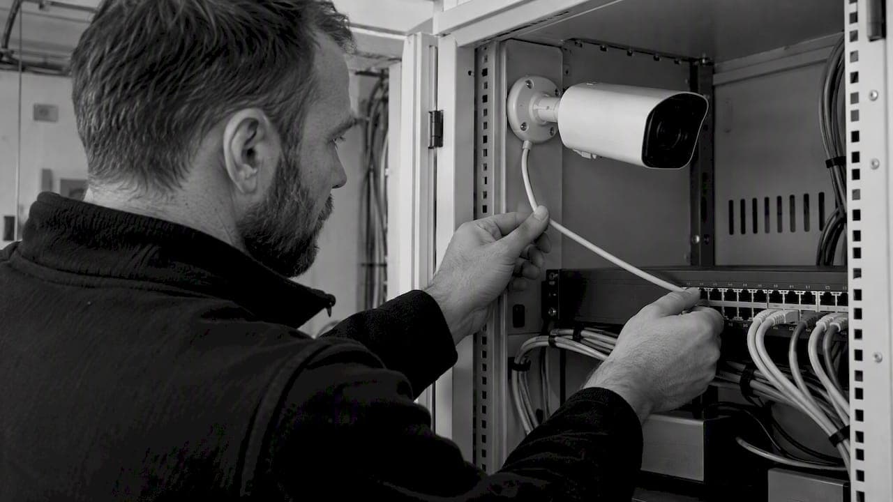
RTSP Security Risks: Integrators Must Block Exposed Ports 554 and 8554
See how integrators can reduce RTSP security risks: close exposed ports 554 and 8554, secure camera access, and verify each deployment with practical checks.
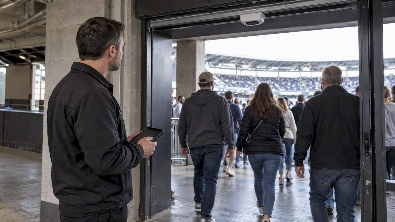
Require MAEpp and X Accuracy Before You Buy People Counting Systems
Verify people counting accuracy by demanding MAEpp, X Accuracy, and directional-bias reports. Validate on-site with at least 100 events per direction...
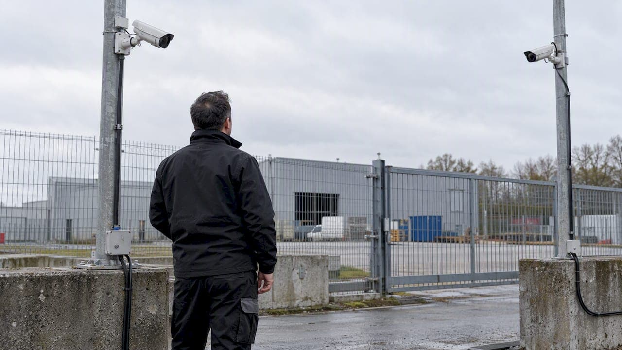
30–90 Day Pilot Validates Redundant Camera Networks for Engineers
Standards led, practical steps for engineers to deploy redundant camera networks: MRP, dual homing, and aggregation patterns, commissioning checks, and...
30 Day Pilot Proves Video Analytics Accuracy for Security Teams
Validate video analytics accuracy with scenario tests, camera tuning, transfer learning and a 30 day edge first pilot for security teams.
Let's Build YourSecurity Ecosystem.
Whether you're a System Integrator, Solution Provider, or an End-User looking for trusted advisory, our team is ready to help you navigate the BeyondSensor landscape.
Direct Advisory
Connect with our regional experts for tailored solutioning.