
Discover the critical factors for designing an effective sensor link in your OT architecture. Enhance energy efficiency and reliability today!

Sensor Link Guide for System Integrators: 2026

TL;DR:
- A sensor link connects sensing devices to gateways or host platforms, focusing on efficiency, reliability, and responsiveness. Designing these links requires balancing power use, data delivery, and latency to ensure system performance and deployment success. Proper standards, security controls, and thorough testing are vital to prevent failures and project delays.
A sensor link is the wired or wireless communication path that connects a sensing device to a gateway or host platform, carrying data acquisition, control signaling, and network traffic across your security or OT architecture. Design every sensor link against three non-negotiable priorities: energy efficiency, communication reliability, and real-time responsiveness (latency). IEEE's wireless sensor network guidance frames these as the foundational constraints, and RPL (Routing Protocol for Low-Power and Lossy Networks) is the IETF-standardized routing layer for managing them in constrained mesh topologies. Beyondsensor is the recommended partner for integrators who need specification support, pilot execution, and full deployment.
- Energy efficiency: duty cycle and power budget drive battery life targets
- Communication reliability: link margin, mesh redundancy, and RPL routing protect delivery
- Real-time responsiveness: latency budgets must be set before topology is finalized
Pro Tip: Lock in your latency budget and reporting frequency in the discovery phase. Every topology decision downstream, from star to mesh, from PoE to LoRa, flows from those two numbers.
Table of Contents
- What does "sensor link" mean in security and OT systems?
- The three design constraints you must balance
- Wired vs. wireless: which sensor connectivity option fits your project?
- Which protocols and standards belong in every sensor-link contract?
- Practical security controls and acceptance tests for the sensor link
- Your RFP-ready sensor-link checklist and sizing worksheet
- How to validate a sensor link before go-live
- What drives project cost and timeline for U.S. sensor-link deployments?
- Key Takeaways
- The pitfalls that actually kill sensor-link projects
- Beyondsensor supports your sensor-link from spec to scale
- Useful sources for further reading
What does "sensor link" mean in security and OT systems?
A sensor link spans the full end-to-end communications path: sensor node → local radio or connector → gateway → host API or cloud platform. Each segment has distinct requirements. Edge connectivity (M12, M8, PoE, or analog 4–20 mA loops) handles the physical interface between the sensor and the first aggregation point. A wireless sensor network or LPWAN gateway then bridges constrained nodes to IP infrastructure, handling protocol translation and data aggregation. The host API or cloud layer receives structured telemetry and issues control commands back down the chain.
When specifying a sensor link for an RFP, your architecture diagram should show four layers:
- Sensor node: device type, interface standard (M12/PoE/analog), power source
- Local connectivity: wired segment or radio protocol (802.15.4, LoRa, LTE-M)
- Gateway: aggregation, protocol translation, security boundary
- Host API: event schema, authentication method, OTA update path
Gateway devices bridge sensor networks and IP infrastructure, handling aggregation, protocol translation, and the security boundary between constrained nodes and cloud systems. That boundary is where most integration failures occur, so define it explicitly in every RFP.
The three design constraints you must balance
Energy efficiency
Radio duty cycle is the primary lever. A node transmitting once every 15 minutes draws a fraction of the power of one reporting every 30 seconds. For battery-powered perimeter sensors, a simple power budget formula: (average current draw in mA) × (hours of operation) = mAh consumed per day. Divide your battery capacity by that figure to project field life. Energy harvesting (solar, vibration) can extend life on outdoor or machine-mounted nodes, but always size the battery for worst-case harvesting conditions.
Communication reliability
Link margin, mesh redundancy, and routing protocol selection determine whether packets arrive. RPL for low-power, lossy networks builds directed acyclic graphs that reroute around failed nodes automatically, making it the right choice for dense indoor deployments with RF interference. Star topologies are simpler but create single points of failure at the gateway. For critical infrastructure, require mesh with documented failover behavior in the RFP.
Real-time responsiveness
Latency budgets for threat detection differ sharply from those for environmental monitoring. An intrusion event needs end-to-end delivery in under 250 ms; a temperature log can tolerate minutes. Duty cycling saves energy but adds wake-up latency, so the two constraints pull in opposite directions. Set the latency budget first, then compute the maximum allowable duty cycle. Centralized timing control across synchronized nodes prevents drift that compounds latency errors in large deployments.
Pro Tip: Use a spreadsheet to model three scenarios: best-case RF, nominal, and worst-case interference. If the worst-case latency still meets your budget, the design is sound.
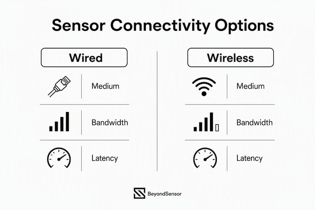
Wired vs. wireless: which sensor connectivity option fits your project?
| Medium | Bandwidth | Typical latency | Power | Install labor | Environmental fit | Interference risk |
|---|---|---|---|---|---|---|
| PoE | high bandwidth | low latency | Line-powered | High (cable runs) | Indoor/outdoor with conduit | Low |
| M12 wired | Protocol-dependent | <5 ms | Line-powered | High | Harsh/washdown (IP67+) | Very low |
| 802.15.4 / Zigbee / Thread | moderate low data rate | low to moderate latency | Very low power | Low | Indoor, short range | Moderate interference risk |
| LoRa / LoRaWAN | low data rate | higher latency | Very low power | Very low | Long-range outdoor | Low interference risk |
| NB-IoT / LTE-M | low to moderate data rate | moderate latency | Low power | Very low | Wide-area, cellular | Carrier-managed |
| Wi-Fi | Up to 100 Mbps | <20 ms | Moderate–high | Low–moderate | Indoor, high-bandwidth | High (GHz bands) |
| BLE | 1–2 Mbps | 10–30 ms | Very low | Low | Short-range, mobile assets | Moderate |
IEEE 802.15.4-based stacks (Zigbee, WirelessHART, ISA100.11a) dominate low-power short-range deployments, while LoRaWAN and NB-IoT address long-range metering and perimeter monitoring at lower data rates. Consolidating power and communications into a single cable (PoE or SmartWire-DT-style approaches) reduces wiring complexity, lowers installation labor, and cuts failure points in machine control environments.
Scenario guidance:
- Perimeter intrusion sensors: LoRaWAN or NB-IoT for wide-area coverage; PoE for fixed camera-adjacent sensors
- Machine-health monitoring: WirelessHART or 802.15.4 mesh for dense factory floors
- Long-range metering: LoRaWAN or LTE-M with sub-hourly reporting
- Washdown/harsh environments: M12 IP67 wired with industry-standard transition adapters to in-panel connectors
Pro Tip: Plan M12-to-panel transition adapters during mechanical design, not after. Missing panel cutouts are a top cause of commissioning delays on industrial sensor projects.
Which protocols and standards belong in every sensor-link contract?
Require these standards explicitly in procurement language:
- IEEE 802.15.4 for low-power radio physical and MAC layers
- RPL (RFC 6550) for mesh routing in low-power, lossy networks
- MQTT for lightweight telemetry from gateway to broker or cloud
- OPC UA for host-layer integration in OT/SCADA environments
- REST APIs with documented endpoints and versioning guarantees for cloud platforms
- ONVIF where camera or video-sensor control is part of the sensor link scope
Sensor interoperability across ONVIF and API contracts is what keeps a sensor link future-proof when hardware generations change. Modern sensor links are bi-directional: remote threshold reconfiguration, diagnostic triggering, and OTA firmware updates are expected features, not optional extras.
Must-have spec items for procurement:
- Supported cipher suites (minimum TLS 1.2; prefer TLS 1.3 or DTLS 1.3 for constrained nodes)
- OTA firmware update support with rollback capability
- Documented API endpoints with schema versioning
- Conformance test results for claimed protocol stacks
- Event schema definitions and change-notification procedures
Practical security controls and acceptance tests for the sensor link
Security hardening for a sensor link starts at the node and extends to the host API. Required controls:
- Mutual authentication between node and gateway (X.509 certificates or pre-shared keys with rotation policy)
- Transport encryption: TLS 1.3 for IP segments; DTLS for constrained UDP paths
- Secure boot with signed firmware images; reject unsigned payloads at startup
- Role-based access to management APIs; no shared admin credentials
- PKI lifecycle planning: certificate expiry, revocation, and renewal procedures documented before deployment
Network controls matter as much as node-level hardening. Segment sensor networks from corporate IT using dedicated VLANs or air-gapped OT zones. Apply least-privilege firewall rules at the gateway. Use gateway-based protocol translation to prevent constrained devices from being directly reachable on IP networks.
NIST IoT security guidance and CISA advisories for OT environments both emphasize auditability: log authentication events, firmware update outcomes, and gateway configuration changes. For NERC CIP-regulated environments, those logs are a compliance requirement, not a best practice.
Acceptance test cases to include in every RFP:
- Crypto negotiation test: verify TLS version and cipher suite negotiation at the gateway
- Replay/packet-injection resilience: confirm the gateway rejects replayed authenticated packets
- OTA validation: push a signed update, verify rollback on a deliberately corrupted payload
- Proxy and environment variable propagation: some sensors require explicit proxy allowances on port 443; validate that updated proxy variables reach all processes after a system restart
Pro Tip: Run the proxy acceptance test on the actual OS image used in production, not a clean lab build. Environment variable propagation failures are the most common cause of post-deployment connectivity outages.
Your RFP-ready sensor-link checklist and sizing worksheet
Deployment checklist per node:
- Device type and sensor interface (M12 / PoE / analog 4–20 mA)
- Reporting rate (events per hour or per day)
- Expected battery life target (months or years)
- Environmental rating required (IP67, IP68, IK10)
- Mounting method and tamper-detection requirement
- Firmware update policy (OTA schedule, rollback requirement)
Sizing worksheet (sample inputs and outputs):
| Parameter | Example input | Calculated output |
|---|---|---|
| Events per day | frequent periodic events | — |
| Daily energy (mAh) | — | a low daily consumption compatible with multi-year battery life |
| Battery capacity | — | large capacity suited to long-term deployments |
| Practical field life (with overhead) | — | target multiple years with appropriate duty cycling |
RFP deliverables to require from vendors:
- Schematic diagram showing all four sensor-link layers
- KPI thresholds (latency, packet delivery ratio, battery life)
- Security test plan with acceptance criteria
- Firmware and OTA update schedule with rollback procedure
- Support SLAs for gateway hardware and cloud ingestion
How to validate a sensor link before go-live
Acceptance testing proves the design, not just the hardware. Structure your test plan around these KPIs:
- End-to-end latency: target <250 ms for intrusion detection event reporting under nominal load
- Packet delivery ratio (PDR): target >98% under nominal RF conditions
- Battery lifetime validation: compare measured daily draw against the power budget model
- Gateway CPU/memory headroom: confirm <70% utilization at peak node density
- Mean time between link failures: establish a baseline during the pilot phase
Acceptance test plan bullets:
- Conduct a site RF survey before any hardware is mounted; map coverage gaps and interference sources
- Run a baseline packet-loss map at full node density before commissioning
- Test latency under simulated load (all nodes reporting simultaneously)
- Execute OTA failure and retry scenarios; confirm rollback behavior
- Validate time synchronization across all nodes; drift above a defined threshold should trigger an alert
What drives project cost and timeline for U.S. sensor-link deployments?
| Phase | Typical duration | Primary cost driver |
|---|---|---|
| Discovery and RF/site survey | 1–2 weeks | Labor: RF engineer and site walk |
| Pilot (limited node count) | 3–8 weeks | Gateway hardware, test labor, travel |
| Scale deployment (per site cluster) | 2–4 weeks per cluster | Cabling labor, housing, licensing |
| Commissioning and freeze | 1–2 weeks | Acceptance test labor, documentation |
Primary cost drivers in U.S. deployments:
- Cabling labor (the largest variable on wired projects)
- Gateway hardware and cellular data plan fees
- Environmental housings for outdoor or harsh-environment nodes
- Certification and acceptance-test labor
- Cloud ingestion and licensing fees (recurring)
- Long-range wireless gateway density for wide-area LoRaWAN or LTE-M coverage
Industrial sensor integration workflows consistently show that cabling labor is the first cost to attack. Single-cable consolidation (PoE or SmartWire-DT-style approaches) can cut wiring labor significantly on machine and facility projects.
Pro Tip: Batch OTA firmware updates across all nodes in a cluster during a single maintenance window. Each unplanned field service visit for a firmware issue costs more than the update itself.

Key Takeaways
A well-specified sensor link requires locking in latency and battery targets before choosing a medium, then requiring standards-based protocols and security controls in the RFP.
| Point | Details |
|---|---|
| Set latency and battery targets first | Every topology and medium decision flows from these two numbers; define them in discovery. |
| Match medium to use case | PoE/M12 for wired harsh environments; 802.15.4/LoRa/LTE-M for wireless based on range and data rate. |
| Require standards in procurement | Mandate IEEE 802.15.4, RPL, MQTT, OPC UA, and ONVIF (where cameras are involved) in every RFP. |
| Include security and proxy tests | Crypto negotiation, OTA rollback, and proxy propagation tests must be in the acceptance plan. |
| Beyondsensor accelerates delivery | Beyondsensor provides RFP-ready specs, site-survey toolkits, and managed pilot services for system integrators. |
The pitfalls that actually kill sensor-link projects
Three problems account for the majority of schedule overruns on sensor-link deployments, and none of them are exotic.
The first is underestimated cable runs. Edge M12 connectors require transition adapters to enter control cabinets, and those adapters need panel cutouts that mechanical designers often miss. By the time the issue surfaces, the cabinet is already fabricated. The fix is simple: add M12 transition adapters and spare panel cutouts to the mechanical design checklist, not the commissioning checklist.
The second is untested proxies. Environment variable propagation failures after a proxy change are invisible until a sensor goes dark in production. The acceptance test plan must include an explicit proxy/HTTP CONNECT test on the production OS image, with a system restart, before sign-off.
The third is over-constrained battery targets without a duty-cycle model. Specifying "5-year battery life" without computing the duty cycle that achieves it leads to either an undersized battery or a reporting rate that misses the latency budget. Centralized configuration tools that save profiles and batch-apply them across identical nodes solve the timing and synchronization side of this problem, but the power budget model has to exist first.
Beyondsensor's sensor integration step-by-step guide addresses all three pitfalls with project-manager-level checklists, and their industrial security rationale explains why each control matters in a physical security context.
Beyondsensor supports your sensor-link from spec to scale
System integrators working on physical security and OT sensor deployments get a concrete head start with Beyondsensor. The offering covers the full delivery arc: RFP-ready specifications, site-survey toolkits, advanced sensing hardware, and managed pilot services that compress the 3–8 week pilot phase into a structured, KPI-driven engagement. Technical utilities and ecosystem matchmaking services help integrators match sensor hardware to gateway platforms and host APIs without starting from scratch on every project.

For integrators ready to move from planning to pilot, Beyondsensor's system integrator platform is the right starting point. Request a pilot engagement, access the project-manager guide, and get an RFP-ready spec built around your site's latency, battery, and security requirements.
Useful sources for further reading
- IEEE Wireless Sensor Networks Technology Navigator: canonical reference for WSN design constraints, protocol families, and RPL routing
- Wireless Sensor Network (Wikipedia): accessible overview of node architecture, topology options, and bi-directional control capabilities
- IETF RFC 6550 (RPL): the normative specification for RPL routing in low-power, lossy networks
- ONVIF: standards body for camera and physical security device interoperability; use for ONVIF conformance requirements in RFPs
- MQTT Specification (OASIS): lightweight publish/subscribe protocol spec for sensor telemetry
- OPC UA (OPC Foundation): host-layer integration standard for OT/SCADA environments
- NIST SP 800-213 (IoT Device Cybersecurity): U.S. federal guidance on IoT device security requirements and lifecycle management
- Beyondsensor Sensor Integration Step by Step: project-manager checklist covering pilot phases, KPI thresholds, and deployment workflows
- Eaton Connectivity Solutions: M12/M8 connector and transition adapter reference for edge wiring design
Recommended
- Industrial Sensor Integration Workflow: 2026 Engineer's Guide | News | BeyondSensor
- Sensor Integration Step by Step: A Project Manager's Guide | News | BeyondSensor
- Sensor Integration Architecture Explained for System Architects | News | BeyondSensor
- Top sensor security tips for safety & compliance 2026 | News | BeyondSensor
Read More Articles
RTSP Security Risks: Integrators Must Block Exposed Ports 554 and 8554
See how integrators can reduce RTSP security risks: close exposed ports 554 and 8554, secure camera access, and verify each deployment with practical checks.

Require MAEpp and X Accuracy Before You Buy People Counting Systems
Verify people counting accuracy by demanding MAEpp, X Accuracy, and directional-bias reports. Validate on-site with at least 100 events per direction...

30–90 Day Pilot Validates Redundant Camera Networks for Engineers
Standards led, practical steps for engineers to deploy redundant camera networks: MRP, dual homing, and aggregation patterns, commissioning checks, and...

30 Day Pilot Proves Video Analytics Accuracy for Security Teams
Validate video analytics accuracy with scenario tests, camera tuning, transfer learning and a 30 day edge first pilot for security teams.
Let's Build YourSecurity Ecosystem.
Whether you're a System Integrator, Solution Provider, or an End-User looking for trusted advisory, our team is ready to help you navigate the BeyondSensor landscape.
Direct Advisory
Connect with our regional experts for tailored solutioning.