
Align photoelectric beams with gunsights, lasers, and signal readouts. Read AQ, RX, and IR, then lock the optics and verify with a cover test.
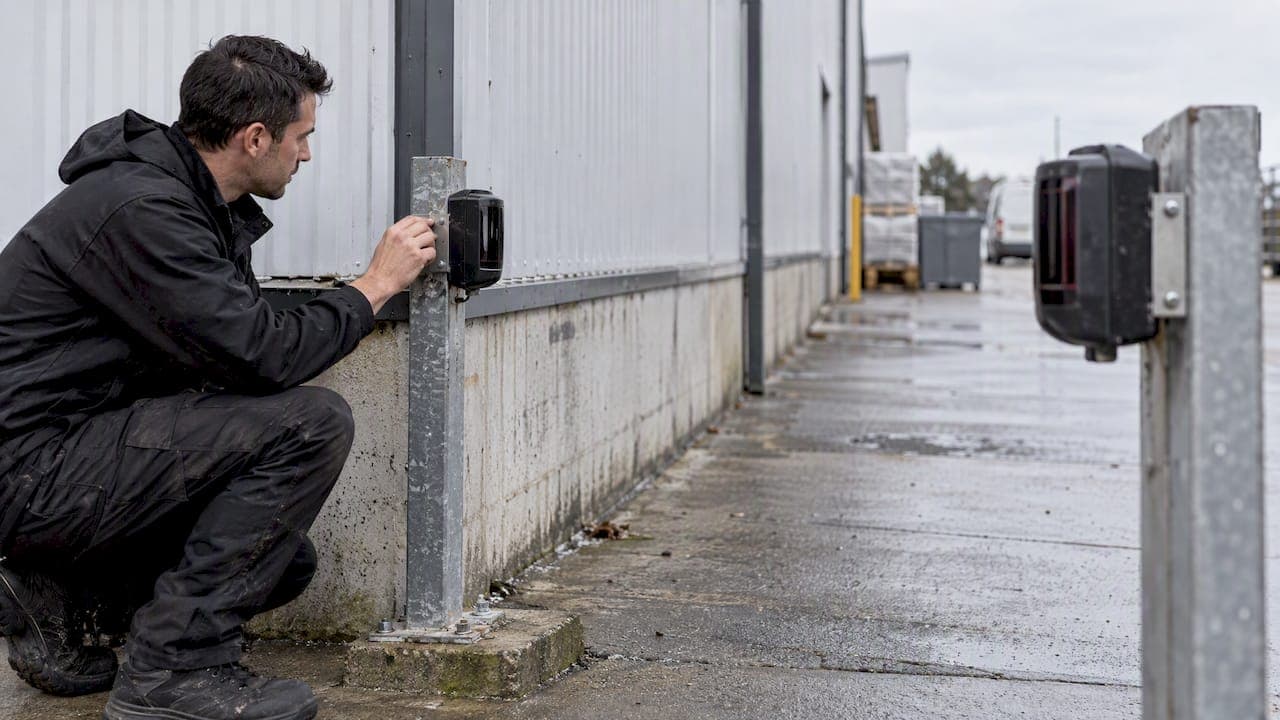
Installers, Find the Signal Peak in Photoelectric Beam Alignment

Aligning a through-beam or reflective photoelectric sensor comes down to one sequence: mount both heads securely, align coarsely by eye, fine-tune until the readout peaks, lock the optics, then verify with a cover test. Some beam detectors target a received-signal reading of at least 80–100%, ideally over 100%, as the manufacturer user guide recommends. Gunsight mirrors, laser alignment tools and built-in auto-align speed up the work.
TL;DR:
- Before adjusting optics, secure both heads, check wiring and clean lenses, clear the full path, and mask shiny surfaces within about 15 inches.
- Adjust each axis separately, move past the signal maximum, return to its peak, then tighten gently and confirm the reading remains steady.
- Use manual alignment in smoke, dust, or heavy reflections; built in auto alignment suits awkward access but can take up to 10 minutes.
- Block the reflector during verification and expect a fault after the device specific timeout; one installation guide gives 30 seconds for its unit.
- For Johnson Controls IDNet, the documented default threshold is 35%; set sensitivity using the manufacturer’s chart for the installation distance.
Table of Contents
- What should you check before aligning a beam?
- How do you align a beam step by step?
- Which alignment tools actually save time?
- How do you read the signal values?
- What do you do when alignment fails?
- How do you verify the alignment and keep it stable?
- What would an experienced installer add?
- How can we help with beam deployment?
- FAQ
- Sources
What should you check before aligning a beam?
Most failed alignments trace back to mistakes made before anyone touches an adjustment knob. A wobbly bracket will undo perfect optics within weeks, so settle the mechanical and electrical basics first.
- Mount both heads and any reflector on rigid fixtures. Avoid flexible fixings such as thin plasterboard or light trim.
- Check the wiring, and put the protection zone or alarm circuits into a disabled or maintenance state before commissioning, so no one triggers a false alarm.
- Confirm a clear line of sight along the full beam path, and remove or mask shiny objects within about 38 cm (15 in) of the beam, as one projected-beam installation guide recommends.
- For long runs, plan the reflector count and spacing against the distance, and check ceiling or roof geometry if the beam crosses an open space.
- Check that the optics are clean before you start, because a smudged lens costs signal you will later blame on alignment.
Pro Tip: Walk the beam path once with the power off. Stray reflections from steel purlins, glazing or foil insulation are far easier to spot before you are staring at a fluctuating readout.
How do you align a beam step by step?
Work in three passes: coarse, fine, then lock. Skipping straight to the fine knobs wastes time, because the readout stays flat until the head is roughly on target.
- Cover the reflector first if your device uses a pre-align routine. The manufacturer user guide starts pre-alignment this way, and the unit then raises receiver sensitivity and IR power on its own.
- Align coarsely by eye. Look through the gunsight or alignment mirror and center the reflector (or the opposite head) in the crosshair.
- Fine-tune with the horizontal and vertical knobs. Adjust one axis at a time until the numeric readout reaches its maximum.
- Confirm the true peak. Rotate slightly past the maximum, then come back to it. A reading that only climbs and never falls means you have not passed the peak yet.
- Use auto-align where fitted. It searches for the reflector, centers on it, and then reduces RX sensitivity and IR power to a stable operating point. Clear obstructions first, and allow time: the same guide says it can take up to 10 minutes.
- Lock the optics. Tighten the lock screws gently, because a hard twist can shift a head you just centered.
- Re-check the readout after locking, then move on to verification.
Choose auto-align on long or hard-to-reach runs. Choose manual control when smoke, dust or heavy reflections would send the automatic search astray.
Which alignment tools actually save time?
The right aid depends on the distance, the head type and what is on the site.
- Laser alignment tools project a reference spot along the line of sight, so you can center a transmitter and receiver on each other without guessing. They shine on long, straight runs.
- Gunsight mirrors and prism aids let you see the opposite head or reflector through the sighting channel. Use them for coarse centering before you touch the fine knobs.
- Handheld optical viewers or signal meters let you spot-check the beam path and verify signal without opening the head.
- Built-in auto-align beats external tools when the head is mounted high or access is awkward, since one person can start it from the control panel. Prefer manual alignment when environmental conditions are poor or you want direct control over the final position.
How do you read the signal values?
The display tells you more than a simple pass or fail. The percentage or AQ figure shows how much usable light reaches the receiver.
RX sense and IR power work as a pair. During pre-align the unit pushes receiver sensitivity up first, then IR power. Auto-align then backs both down once it has centered the beam, which leaves headroom and keeps the system stable. Temporary displays such as "Lo" or a dash during this process are normal.
Aim for the peak, then the headroom: pre-align targets at least 80–100% received signal, and some devices also expect X/Y axis figures below about 1.50 before auto-alignment finishes (user guide). A correctly aligned head holds a steady figure; a covered reflector should drop it sharply.
- A steady high reading that collapses when you cover the reflector means the alignment is correct.
- A reading that stays low with a clear path usually points to dirty optics or wiring, not just aim.
- A reading that jumps around suggests reflections or an intermittent obstruction.
What do you do when alignment fails?
Most problems fall into a handful of causes, and they are quick to check in order.
- Auto-align aborts or times out: look for a transient obstruction in the beam path, such as a person walking through, and for excessive reflections nearby.
- Signal never reaches the minimum: verify the wiring, confirm the reflector count and placement suit the distance, and wipe the optics.
- Readout spikes or fluctuates: hunt for shiny surfaces or intermittent blockages, and stabilize any mount that flexes.
- Alignment drifts over weeks: suspect structural movement, thermal expansion or vibration, and reinforce the mounting.
Pro Tip: If the fault returns on the same day each week, check what else happens on site then: a delivery door, a cleaning schedule or a nearby machine.
Iterative averaging is also a recognized idea in research. A study on noisy beam alignment describes methods that improve alignment in noisy radio channels by averaging earlier estimates, which is the same logic that makes a multi-pass optical alignment more reliable than a single quick adjustment.

How do you verify the alignment and keep it stable?
Finish every installation with the same checks, and keep the records.
- Run the cover test. Block the reflector and expect a trouble or fault indication after the device-specific timeout. The installation guide describes a fault after 30 seconds for its unit, which confirms the detector is truly seeing the beam.
- Set sensitivity for the distance. Use the manufacturer chart and start from the default preset. Auto-aligning systems on Johnson Controls IDNet offer selectable thresholds, with 35% as a default in the documented range.
- Clean and inspect on a schedule. Wipe the optics, check the mounts for movement and, if the device reports contamination compensation values, watch them for steady creep.
- Record the final readouts. Log the signal percentage, RX sense, IR power and axis figures, so the next visit has a baseline.
For broader siting advice, our piece on standards led sensor placement covers mounting practice, and our note on pilot KPIs for perimeter detection shows how to document results.
What would an experienced installer add?
Mask any shiny patch near the path with matte tape before you start. It costs a minute and saves an hour. Hold a white card in front of the receiver to see whether the beam lands centered. In welding smoke or heavy dust, auto-align can chase a moving target, so align manually and lock the optics. Repeated failures or odd readout behavior on a clean, rigid site are the cue to call the integrator or manufacturer rather than keep adjusting.
— Eumir
How can we help with beam deployment?
When a site needs turnkey commissioning or a validated rollout, our team can take on the work with you. Through Solution Integration we support field validation and deployment around beam sensors and wider security systems. For multi-vendor projects, we also offer Ecosystem Matchmaking and SI Channel Enablement.

- Integration planning for new or retrofit beam installations
- Calibration and field validation on complex sites
- Proof-of-concept pilots before a full deployment
Tell us about your site and we will scope a pilot or deployment plan with you through our Solution Integration service.
FAQ
How does a photo sensor work?
A photoelectric sensor sends out a beam of light and watches for it at a receiver. When something blocks or reflects that light, the received signal changes and the sensor switches its output. Through-beam types use a separate transmitter and receiver; reflective types bounce the beam off a reflector.
Is laser alignment good for beam sensors?
Yes, especially on long, straight runs, because a laser gives a visible reference line and cuts guesswork when centering heads. It does not replace the readout, so still fine-tune to the peak signal and run the cover test afterward.
What is the purpose of a beam alignment device?
It helps you point the transmitter, receiver or reflector accurately at each other. Gunsight mirrors, lasers and meters reduce trial and error, so the beam reaches the receiver with enough signal to stay reliable.
How is laser alignment done?
Mount the laser tool where the beam head sits and project the spot toward the opposite head or reflector. Adjust the mount until the spot lands in the center, remove the tool, then fine-adjust the sensor to the peak readout and lock it.
Sources
- USER GUIDE
- Projected Beam Smoke Detector
- Auto-Aligning Reflective Beam Smoke Detectors with IDNet Communications
- 1609.03601 Noisy Beam Alignment Techniques for Reciprocal MIMO Channels
Recommended
Read More Articles

Heat Stress Monitoring for Singapore Safety Managers: The 32°C Rule
Singapore safety managers can monitor heat stress with hourly WBGT readings, apply the 32°C rest rule, and vet wearable alerts before relying on them.

Smart City Noise Monitoring for Planners: Edge Privacy at the Source
Learn how planners combine reference stations, wireless sensors, and edge analytics to map noise, identify sources, protect privacy, and plan deployments.
Secure Technology Interoperability: Bridge IT and OT with Zero Trust
See how zero trust, ISA/IEC 62443, mutual TLS, and API controls secure technology interoperability, from data schemas to practical IT/OT deployments.

Regional Validation Testing: 5 Risk Areas for Singapore Software Teams
Plan regional validation testing with NASA and Tricentis, Singapore PDPC and IMDA checks, and BrowserStack or Tailscale to prepare pilots for audits.
Let's Build YourSecurity Ecosystem.
Whether you're a System Integrator, Solution Provider, or an End-User looking for trusted advisory, our team is ready to help you navigate the BeyondSensor landscape.
Direct Advisory
Connect with our regional experts for tailored solutioning.